7.2 BASIC LIQUID PROPELLANT ROCKET ENGINE CONTROL SYSTEMS
Most engine systems require several or all of the basic control systems summarized in the following paragraphs. Typical applications are found in chapter III, for the A-1, A-2, A-3, and A-4 propulsion systems (figs. 2-10, 3-3, 3-6, and 3-9).
Engine System Start Control
The prime objective of a start-sequence control is to bring the engine system safely from start signal to main-stage operation. A typical sequence may consist of systems preconditioning (purging, chilldown); application of start energy, if required (start tanks, turbine spinner); and introduction and ignition of the propellants in the main combustion chamber. Secondary sequences may be required for certain subsystems such as the gas generator system. A reliable enginestart sequence is maintained through interlocks and by monitoring each functional step of engine operation during the start transient. The propellant-valve opening sequence is set to effect either an oxidizer-lead or a fuel-lead start. This is usually dictated by propellant type and chamber ignition and cooling methods. Figures , and present typical engine system start and cutoff sequences.
Engine System Cutoff Control
Rapid and safe engine shutdown, during normal operation as well as in an emergency, is desirable for minimum and repeatable cutoff impulse, and to enhance reliable systems operation. The cutoff sequence usually consists of shutoff of subsystems power (gas generator, etc.); shutoff of main chamber power; and, in case of test firings, postfiring securing (purges, flushes). As a rule, the propellant valve-closing sequence is adjusted to provide a fuel-rich cutoff in the main combustion chamber. This prevents damaging temperature spikes and results in smooth and rapid thrust termination.
Engine Main Stage Duration Control
Important considerations governing engine duration have been discussed in section 2.1. The signal for engine in-flight cutoff, unless it is the result of a malfunction, will be supplied by the vehicle and fed directly into the cutoff control system discussed in a preceding paragraph. For lower stages, where optimum utilization of the propellants is desired, a tank lowlevel sensor is often employed. In final stages, where precise cutoff velocity is essential, an integrating accelerometer or equivalent device will signal cutoff.
Engine System Safety Controls
Special monitoring devices, such as combustion stability monitors for detecting combustion instability, gas generator overtemperature sensors, or turbopump overspeed trips, are frequently employed to prevent undesired or unsafe conditions by effecting prompt, automatic, nonhazardous, fail-safe system shutdown during all phases of engine operation. In addition, most engine control systems are designed so that an interruption of electrical power supply will cause the system to shutdown safely. (For certain missions it may be desirable to switch to an emergency power source, or prevent shutdown by mecnanical latching, for continued operation.) Mechanical and electrical interlock devices are extensively used in the control system to assure the reliability of the safety control systems.
Propellant Tank Pressurization Control
Various propellant tank pressurization systems have been discussed in chapter V. The design requirements for the control of these systems must consider- (1) Means to maintain the required tank pressure level within an allowable range during all phases of vehicle and engine systems operation, including steadystate engine mainstage; start or dynamic throttle transients; and vehicle coasting periods between restarts. (2) Effective safety devices such as pressure relief valves to prevent overpressurization and rupture of the propellant tanks. (3) Compatibility with other subsystem controls, such as propellant-utilizationcontrol and thrust-control systems.
Most propellant tank pressurization control systems are of the closed-loop type.
Engine System Control Calibration
The systems described in the preceding paragraphs require proper adjustment and calibration for desired engine operating characteristics and performance. This includes the setting of timing devices, pressure switches, position switches, and the sizing of orifices. The correct values for each of these are verified during engine calibration and checkout firings. Of the orifices, some are placed in propellant lines for performance parameter calibration. Others are used in pneumatic or hydraulic lines as timing and restricting devices. Specific orifice applications for thrust and mixture ratio control will be discussed in sections 7.3 and 7.4; orifice design
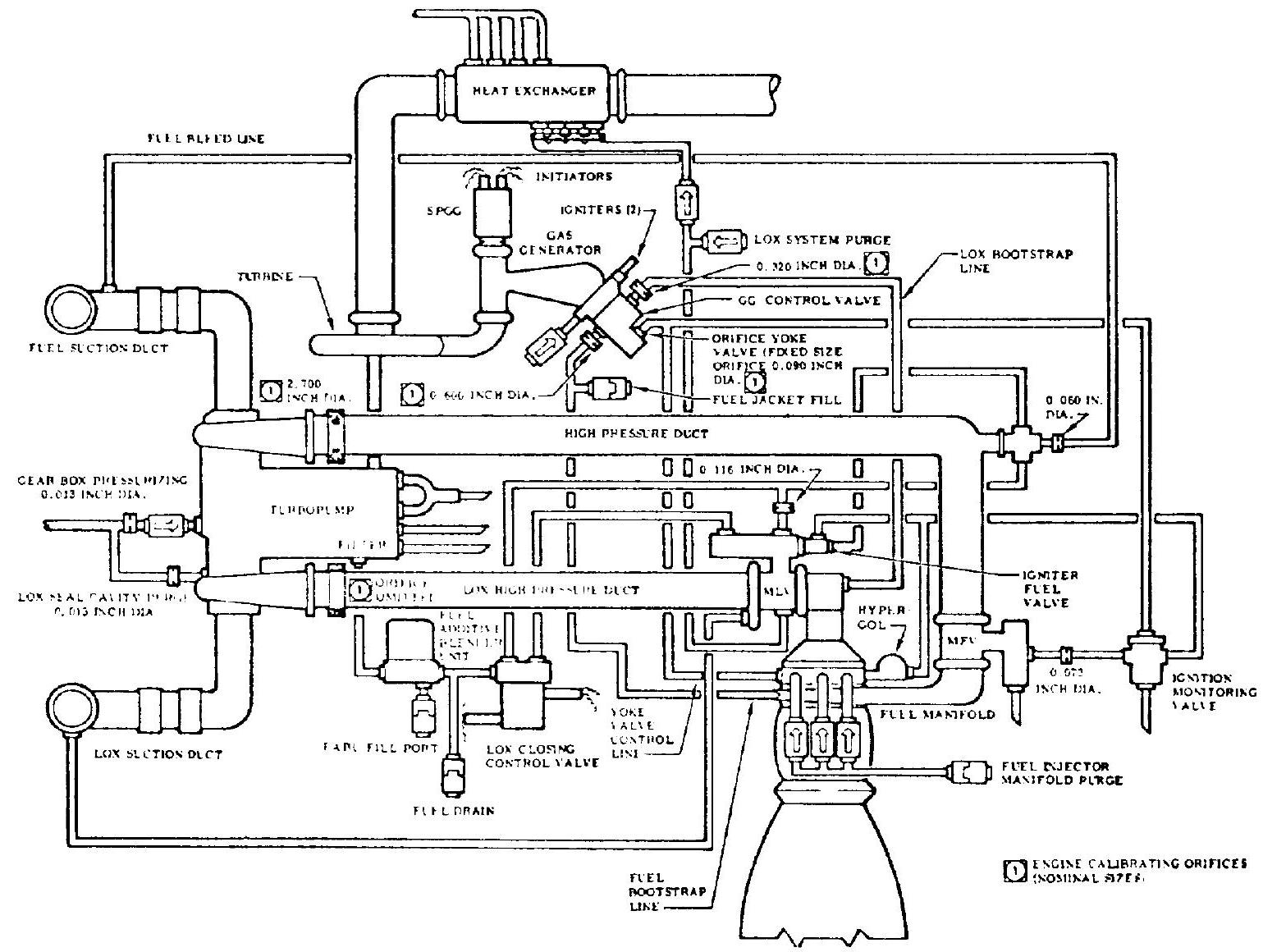 Figure 7-2.-Control orifice locations and sizes of a typical engine system.
elements will be presented in section 7.10. Following sizing, orifices must be properly identified, by stamping or banding, and their actual sizes recorded in the engine logbook. Control and calibration orifice locations and sizes of a typical system are shown in figure 7-2.
Engine Systems Checkout and Test Controls
To verify operational readiness of the engine system and its subsystems, suitable control means are required for postassembly and prefiring checkouts. These permit simulation of the operation of the engine and its critical control components, without actually firing the engine system. Utilizing suitable ground-support equipment (GSE), an engine checkout control system should include- (1) Provisions to conduct leak checks and electrical-continuity checks of the entire engine system. (2) Provisions for verifying proper operation of all instrumentation pickups, such as dc bus voltage and spark plug firing monitors; open, closed, and continuous position signals for valves; propellant flowmeters; and pressure transducers. (3) Provisions for verifying the proper function and operating range of all control devices and subsystems, such as flow control valves, pressure regulators, and thrust and mixture ratio control devices. (4) Provisions to simulate vehicle signals for "cold" checkout of the engine system operating sequence, such as for start and cutoff. In addition to the checkout equipment, the engine ground-support system must include equipment to permit control of static test firings. This often requires additional instrumentation.